Menu
The Machine
The Idea
The Brain
The Case
The Keyboard
Main Screen
Mini Screens
TFT Screen
RFID Reader
Using the RFID Reader
Designing RFID Cards
LED Lighting
Power Displays
GPS Module
Battery Power
Power Switch
3D Printed Parts
Future Plans
Problems
With the original hardware removed, it leaves a free area to the right of the screen. It seems that it was there for a place to put your notebook when you're using the machine.
With that space available, it was sitting above the dual floppy drive location so there is quite a lot of space available & it has to be used by something.
That something will be 3 screens. 2 LED & 1 OLED giving the user some system information.
So, first we have to figure out where to put the screens. That's where LightBurn came in useful so I could mock it all up and print out life size templates that were stuck onto the piece.
Download lcd-layout.lbrn2 (39.7Kb)
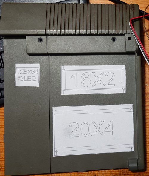
So now we have out screen layout, we have to figure out what to put on it & code it up. With all that done (and some creative wiring for using the i2c bus) we have something like this running
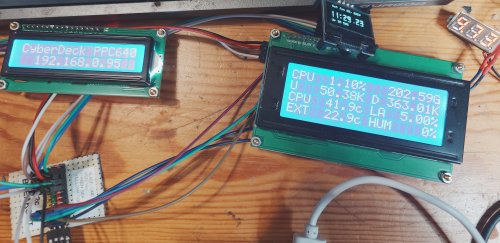
What information does it show?
- CPU Usage
- CPU Temperature
- External Temperature
- Data Uploaded
- Data Downloaded
- Load Average (as a percentage)
- Humidity (if it works)
- Local Time & Date
- Uptime
- Local IP address / Processor speed as a graph
- Information Message
The breadboard in the bottom left is the i2c breakout board as mentioned above so the system can use more than 1 item on that bus! More about that later.
Let us now switch back to the actual plate that we saw in early mockup above.- The holes have been cut but not finised as well as what it will look like at the install stage
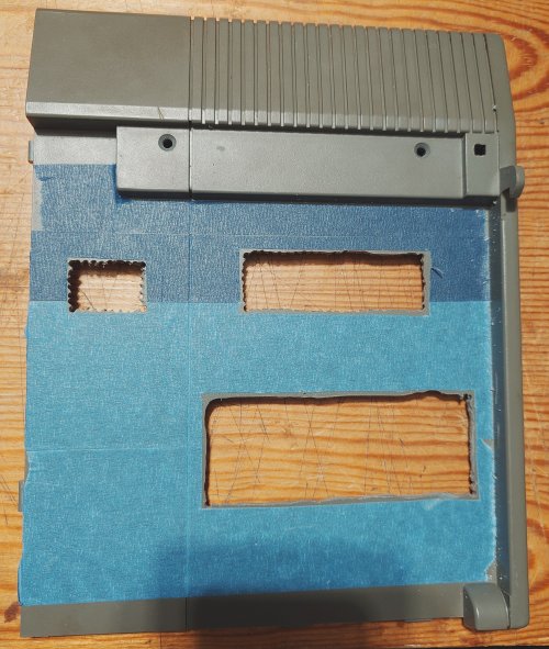
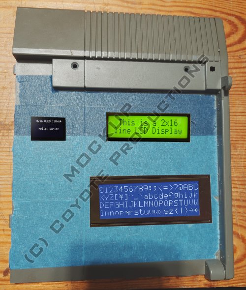
Finally, after a couple of hours work, the piece was finished & ready to have the screens mounted. The lighting is showing a different colour than what it looks like in real life but the work was finished! Now, the screens will be inserted and this part of the project can be crossed off the list!
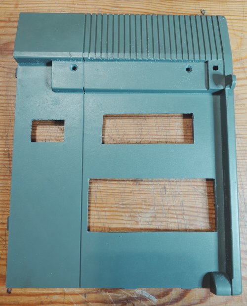
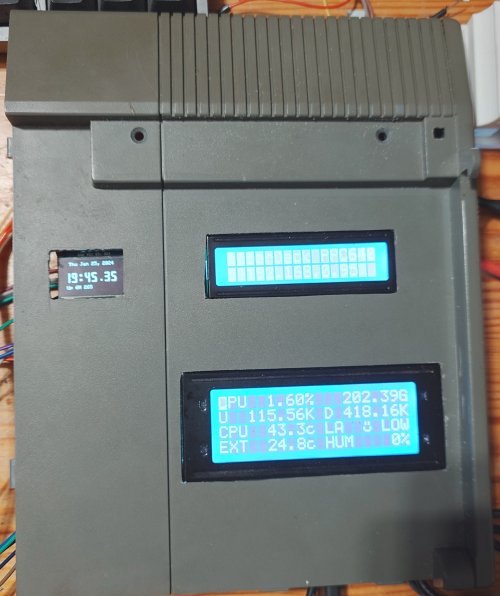
With the holes finally finished, the screens can be test fitted. They mostly fit but could do with some more work as you can see
